
Department of the Army Technical Manual TM 10-751
Organist's Manual for Electronic Organ
AN/TNP-1
Department of the Army • December 1949
SECTION II
DESCRIPTION
3. General
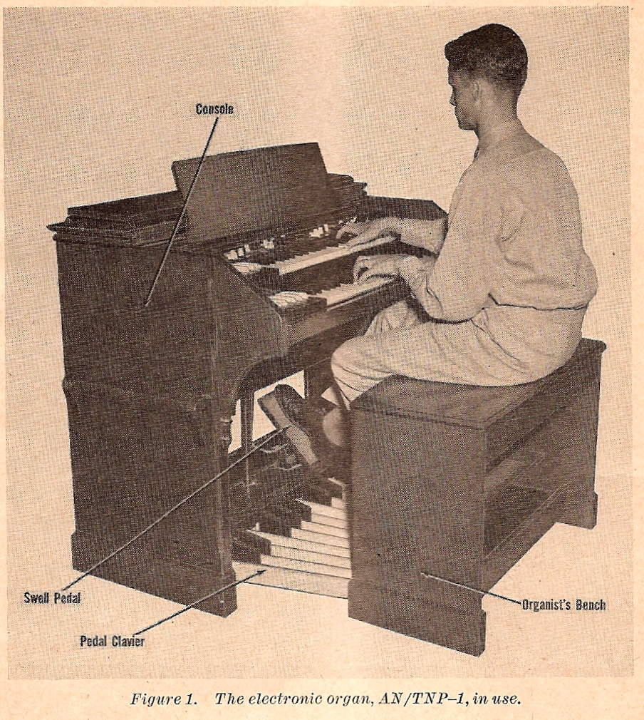
The complete electronic organ, AN/TNP-1, is a self-contained, electromechanical, sound-producing unit designed for operation on 120-volt, 60-cycle alternating current, or 120-volt, 50-cycle alternating current, as indicated on name plate, (see fig. 1). It makes use of the physical characteristics of sound to build musical tones from fundamental sounds that are electrically produced. The complete organ, consisting of a console, a tone cabinet, and auxiliary equipment, is a movable unit which fits into a space approximately 4 feet square.
4. Console
The console is a wooden cabinet similar in size and shape to the conventional pipe organ console. It contains the equipment required to select, generate, control, and partly amplify musical tones.
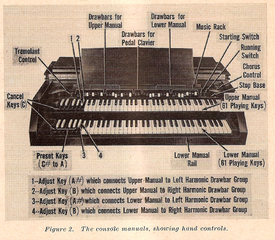
a. Hand Controls. The console has a slanting cover at the front that folds back upon the console top to reveal all hand controls used by the organist to produce music. Hand controls consist of manuals, drawbars, and various switches and other control devices (see fig. 2).
- Manuals. Two manuals (keyboards played with the hands) are on the front of the console at playing level. They are in two horizontal tiers, the upper lying to the rear of the lower in stairstep fashion. The two manuals are identical, each consisting of 73 keys in two sizes. The color scheme of the 61 keys at the right of each manual, called playing keys, is exactly reverse to that of the remaining 12 at the left, called preset keys.
-
- (a) Playing keys. The 61 playing keys are colored in conventional piano or organ fashion, having 25 short black keys indented in the usual pattern between 36 longer white keys. Contacts required to produce musical tones are made by pressing lightly on the-playing keys.
- (b) Preset keys. The 12 preset keys have a color scheme in an order reverse to that of playing keys, having 5 short white keys indented between 7 longer black keys. Tone selection keys consist of a cancel key, C, to the left of 9 preset keys and 2 adjust keys. Operation of preset keys, C # to A inclusive, allows the organist to select one of nine predetermined tone qualities for the 61 playing keys. Operation of the 2 right-hand adjust keys, A# and B, gives flexibility to tone selection, since these keys are connected through additional quality selection equipment known as drawbars.
- Drawbars. Drawbars are a series of push-pull knobs mounted on a vertical panel at the rear of the upper manual. There are 38 drawbars arranged in five groups. Two identical groups of 9 drawbars each at the left are separated from two other identical groups of 9 drawbars each at the right by a group of 2 brown drawbars in the center.
-
- (a) Harmonic. The four groups of 9 drawbars each are known as harmonic drawbars. The two groups to left of center are connected to the 2 right-hand tone selection adjust keys, A# and B, on the upper manual. The two groups to right of center are connected to the same 2 keys on the lower manual. The color scheme of each group of 9 drawbars is in the following order from left to right: 2 brown drawbars followed by 2 white, a black, another white, 2 more black, and a final white. Each drawbar controls a small metal' strip that is pulled outward from a silent position to any of eight gradations of volume. Tonal quality is also affected by the settings of these bars.
- (b) Pedal. The 2 brown drawbars in the center of the harmonic drawbars are known as pedal drawbars. They operate in the same way as harmonic drawbars, each controlling the volume and tonal quality of the pedal tones.
- (3) Starting switch. The starting switch is the left unit of twin, toggle-type switches mounted together in a bracket above the right end of the upper manual. START and OFF positions' are noted beside the switch.
- (4) Running switch. The running switch is the right unit of the pair noted in (3), above. RUN and OFF positions are noted beside the switch.
- (5) Tremolant control. The tremolant control is a knob mounted above the left end of the upper manual. This knob turns clockwise to increase or counterclockwise to decrease a pleasing tremolo or fluttering of the organ tone. A white dot near the outer edge of the knob shows the relative position of the knob.
- (6) Chorus control. The chorus control is a push-pull knob mounted at the extreme right of the drawbar panel. This knob pulls outward to produce the effect of many organs playing at the same time.
b. Foot Controls. The foot controls, located within easy reach of the organist's feet, include a pedal clavier and a swell pedal.
(1) Pedal clavier. The pedal clavier is an assembly of 25 wooden pedals housed in a wooden framework. It sits at floor level in front of the wooden console cabinet. Pedals are provided in two designs and are colored in conventional organ fashion with 10 pedals having short black elevated foot contacts indented in the usual pattern between 15 flat-topped, light-colored pedals. Each pedal has a flexible metal strip fastened to its console end. When the organ is assembled, these pedal end strips slip into the base of the console cabinet. When pedals are pressed down, the end strips activate the electronic equipment required to transmit the pedal tones.
(2) Swell pedal. The swell pedal is located near the center of the base shelf of the console. It consists of a rubber-padded footpiece connected with the interior of the organ by means of a crankshaft and rod assembly. When the toe of the footpiece is pushed, the organ volume is increased; when the heel is pushed, the volume is decreased.
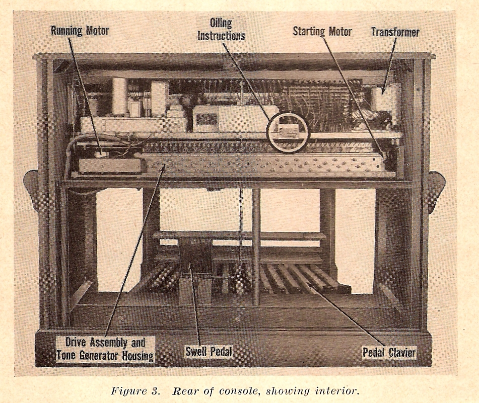
c. Mechanical and Electronic Components. The mechanical and electronic components of the organ console are accessible after the removal of a wooden panel at the rear of the console (see fig. 3).
(1) Mechanical. The mechanical components of the console, consisting of a drive assembly between two motors, are on the console cabinet shelf. The drive assembly, concealed by a housing, consists of a drive shaft and numerous gears. It is started by a shaded pole starting motor located to .its right. When the drive assembly is at operating speed, the shaded pole motor is stopped and released by a clutch from the assembly drive shaft to allow a synchronous-type running motor to keep the assembly operating at constant speed. The synchronous-type motor is coupled to the left of the drive assembly.
(2) Electronic. The electronic components consist of tone generating units concealed with the drive assembly in the tone generator housing, a tremolant switch to produce a tremolo effect in the organ tone, a transformer, and various other equipment for amplifying or producing organ tones.
5. Tone Cabinet
The tone cabinet consists of a wooden housing containing the electrical equipment and loud-speakers required to amplify the musical tones produced in the console (see fig. 4). The cabinet housing is a long, box-shaped structure open at the rear. Its front is a grille through which the organ is heard. The cabinet housing is divided into front and rear compartments by a partition extending lengthwise, parallel to and near the grille. Holes in this partition support, the mouths of four loud-speakers. Loud-speakers are electrically connected to two seven-tube power amplifiers and a reverberation preamplifier located in the rear compartment of the cabinet. An attachment called a reverberation unit is bolted to an upright mounting board on one side of the tone cabinet housing. The purpose of this unit is to lend an echo effect to the artificially formed organ tones, which might otherwise sound disagreeably abrupt.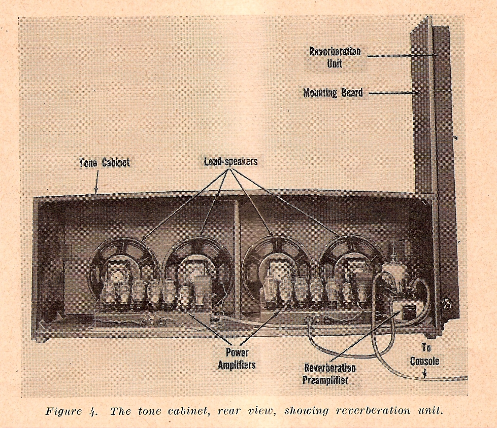
6. Auxiliary Equipment
The auxiliary equipment used with the electronic organ consists of an organist's bench and the cables and plugs required to connect the organ.
a. BENCH. The organist's bench, shown in figure 1, is constructed of wood and designed so that its feet will straddle the framework of the pedal clavier. A wooden strip across the front of the bench, near the bottom, serves as a footrest when the pedal clavier is not in use. The seat of the bench may be raised on hinges at the rear to disclose a long storage compartment under the seat.
b. CABLES AND PLUGS. The console is provided with a 15-foot, two-conductor power cord to connect the console to the alternating current power source. A 35-foot, six-conductor cable, with a six-prong female connector receptacle, is provided for connecting the console to the tone cabinet.